Waterflood
Waterflood
Waterflood Animation
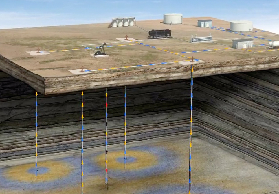
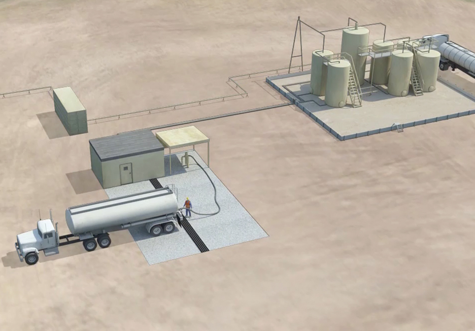
In the primary recovery phase of oil production both gravity and the natural pressure of the reservoir drive oil into the production well. Typically, only about 10 percent of the original oil in the reservoir can be produced in the primary recovery phase. During primary recovery, water that exists naturally in the oil reservoir is produced alongside the oil. Upon reaching the surface, the produced oil and water are separated. The oil is held in storage tanks and then transported for sale. The water, or oilfield brine, is held in a storage tank for later use. Once the pressure in the reservoir has begun to drop, it is necessary to utilize secondary recovery techniques to continue to produce oil from the reservoir at an economical rate. Secondary recovery techniques will help maintain the pressure in the reservoir and extend a well’s productive life. One of the most common secondary techniques, waterflooding, uses the injection of water into the reservoir to drive more oil towards the production well. To prepare for the waterflood process, additional water is brought to the pad site and held in a storage tank. This water will be injected into the reservoir with the previously recovered oilfield brine. Certain production wells are selected as injection wells for pumping water into the reservoir or, if necessary, new injection wells may be drilled. The precise configuration of these wells will vary, but one of the most common is the five-spot pattern. A five-spot pattern has four water injection wells located at the corners of a square, with a producing well at the center. Once the injection wells are established, water is pumped through them and down into the reservoir. As the water enters the reservoir from the injection wells, it creates pressure and sweeps the oil towards the production well. The waterflood process is repeated throughout the field and can recover an additional ten to twenty percent of the original oil in the reservoir. The water is injected until it reaches the production well in large quantities. Once the ratio of water to oil produced from a well becomes too high, it is no longer economical to continue with the waterflood and the process is complete.
Other Educational Animations
Multi-stage Vertical Frac
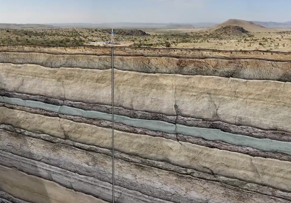
This Multi-Stage Vertical Frac Crude Oil Animation explains and demonstrates how a vertical well is drilled, stimulated and produced from multiple formations to recover hydrocarbons. In this animation, we show a well targeting three sandstone layers. The well is initially drilled to a designated distance below the deepest fresh water source near the surface.
Impact Crater
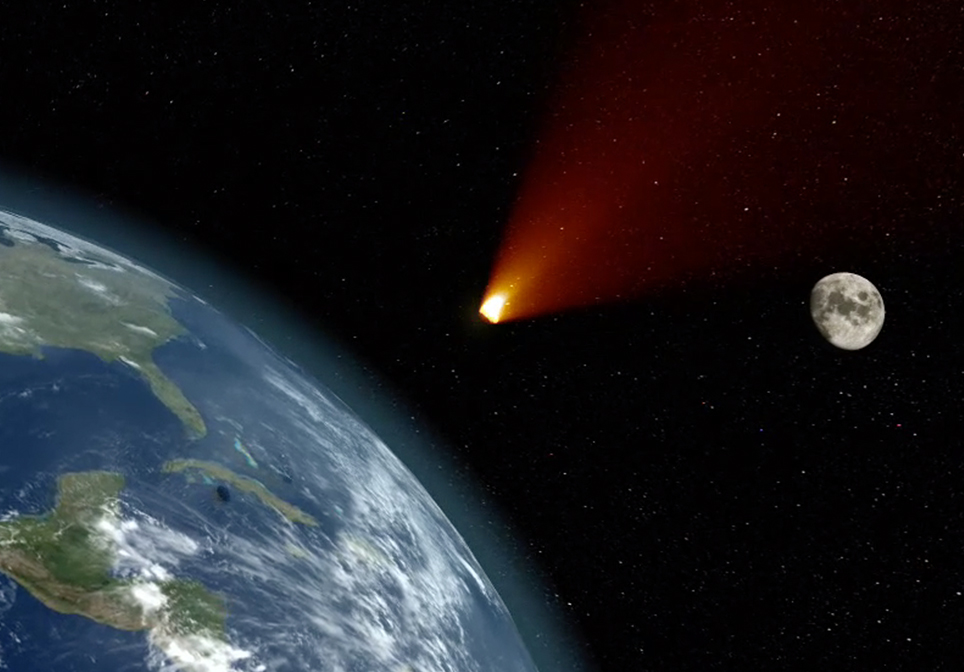
The 10 biggest impact craters on Earth date back from 35 million to over 2 billion years ago.
When an asteroid or meteorite crashes into the surface of a planet or a moon, a circular depression is formed. To form a true impact crater, this object needs to be traveling at super-fast speeds – many thousands of miles per hour! It immediately vaporizes and creates enormous shockwaves through the ground that melt and recrystallize rock and are one of the most destructive forces in the solar system.
The Chicxulub crater, sometimes referred to as the deadliest location on earth, is buried beneath the Yucatán Peninsula in Mexico. When the Chicxulub asteroid slammed into Earth about 66 million years ago, it obliterated 80 percent of Earth’s species, blasted out a crater about 200 kilometers (124 miles) across and 19 kilometers (12 miles) deep, and signaled an abrupt end to the Cretaceous Period.
CO2 EOR Carbon Dioxide Enhanced Oil Recovery
This CO2 EOR Educational Animation – created by John Perez Graphics & Design, LLC – explains the CO2-EOR process. We travel deep in to the Earth’s subsurface to demonstrate injection, miscibility, WAG, and increased oil production.
Saltwater Disposal
This Saltwater Disposal Well Animation – created by John Perez Graphics & Design, LLC – explains the steps necessary when disposing of salt water that is produced when drilling an oil or gas well. The animation takes you from the surface facilities, through the various protective casing strings down several thousand feet to the pre-approved formation zone where the salt water will be disposed of. This follows the EPA preferred method for the disposal of produced saltwater in Class II Saltwater Disposal wells.